Subaru Legacy BN/BS (2015-2019) Service Manual: Removal
1. RADIO ANTENNA AMPLIFIER • Sedan model 1. Disconnect the ground terminal from the battery sensor, and wait for at least 60 seconds before starting work. NOTE 2. Remove the trim panel - rear pillar UPR LH. Rear Quarter Trim > REMOVAL 3. Remove the amplifier assembly - antenna. (1) Disconnect the connector. (2) Remove the bolts, and remove the amplifier assembly - antenna.
• OUTBACK model 1. Disconnect the ground terminal from battery sensor. NOTE 2. Remove the trim panel - rear gate UPR. Rear Gate Trim > REMOVAL 3. Remove the amplifier assembly - antenna. (1) Disconnect the connector. (2) Remove the bolts, and remove the amplifier assembly - antenna.
2. XM SATELLITE RADIO/TELEMATICS ANTENNA 1. Disconnect the ground terminal from the battery sensor, and wait for at least 60 seconds before starting work. NOTE 2. Lower the trim panel - roof assembly. • Sedan model: Roof Trim > REMOVAL • OUTBACK model: Roof Trim > REMOVAL NOTE: Procedures for the trim panel - roof assembly is performed inside the vehicle. 3. Remove the antenna assembly - roof. (1) Disconnect the connector. NOTE: For sedan model with telematics, disconnect the two connectors. (2) Remove the nut, and remove the antenna assembly - roof.
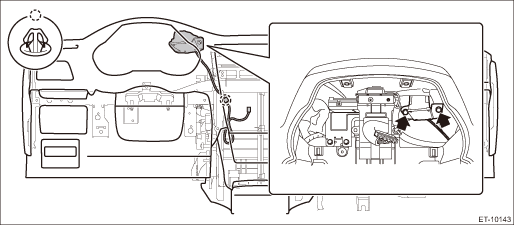
3. ANTENNA FEEDER CORD 1. Disconnect the ground terminal from the battery sensor, and wait for at least 60 seconds before starting work. NOTE 2. Remove the audio assembly or navigation assembly. Audio > REMOVAL 3. Remove the cover assembly - front and the console box assembly. Center Console > REMOVAL 4. Remove the passenger’s seat. Front Seat > REMOVAL 5. Remove the front cover - side sill and the cover side sill - front. 6. Lower the trim panel - roof assembly in the same manner as the removal procedure of XM satellite radio antenna. • Sedan model: Roof Trim > REMOVAL • OUTBACK model: Roof Trim > REMOVAL 7. Turn over the floor mat, and remove the cord assembly - antenna feeder. 4. TELEMATICS SUB ANTENNA 1. Disconnect the ground terminal from battery sensor. NOTE 2. Remove the combination meter assembly. Combination Meter > REMOVAL 3. Remove the center grille assembly. Center Console > REMOVAL 4. Remove the heater control assembly. Center Console > REMOVAL 5. Remove the audio assembly or navigation assembly. Audio > REMOVAL 6. Remove the telematics sub antenna. (1) Disconnect the telematics sub antenna connector on the data communication module side, and tie a string to the connector. NOTE: A string makes operation easier during installation. (2) Remove the screw and harness clamp, and pull out the telematics sub antenna from the combination meter side.
(3) After the telematics sub antenna has been pulled out, remove the string attached to the connector in step (1). |
 Inspection
CAUTION:When wiping dirt off of the glass to avoid heat wire damage, be careful of the following.• Use a dry and soft cloth.• Move the cloth along the heat wire.Inspection method of antenn ...
 Installation
1. RADIO ANTENNA AMPLIFIER1. Install the amplifier assembly - antenna.Tightening torque:12±3 N·m (1.2±0.3 kgf-m, 8.9±2.2 ft-lb)2. Install the trim panel - rear pillar UPR LH. (Sedan model)3. ...
Other materials:
GVWR and GAWR (Gross Vehicle Weight Rating and Gross Axle Weight Rating)
Certification label
The certification label attached to the
driver's side door shows GVWR (Gross
Vehicle Weight Rating) and GAWR (Gross
Axle Weight Rating).
The GVW (Gross Vehicle Weight) must
never exceed the GVWR. GVW is the
combined total of weight of the vehicle,
fuel, driver, all ...


